
Installlation
Fig. 1
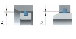
The design for gaps (A) must be as small as possible. The smaller the gap the larger the labyrinth or sealing effect.
Please refer to the information in the respective data sheets for the different ring designs under "Axial and/or radial play" if radial play and/or tilting motions are detected!
Fig. 2
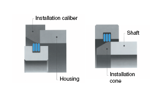
The use of attachable installation tools for the housings and removable installation tools for shafts are recommended if the specified installation chamfers are not possible at the housing or shaft for space reasons.
Do not only press when assembling the parts equipped with rings but overcome the slip resistance by radial motion and axial tapping.
Fig. 3
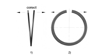
1) Single and double wound laminar rings are spiraled into the grooves by axially spreading the rings.
2) Care must be taken to ensure the rings are not over stretched, as they will be permanently deformed.
Fig. 4
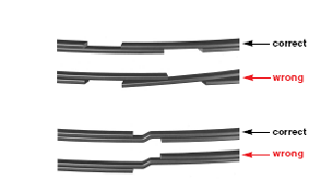
Do not spiral the ring ends into each other or jam them when the single wound laminar rings are spiraled into the grooves.
Do not spiral the ring ends or the windings into each other or jam them when the double wound laminar rings are spiraled into the grooves.
Fig. 5
As shown, inside and outside clamping laminar rings can be installed through spiraling by hand.
Spread ring slightly axially
1) Insert one ring end into the groove.
2) Slide remaining part of the ring spirally.
Fig. 6
The shaft retaining rings can also be installed with a support tool (see figure) to replace spiraling by hand.
1) Attach installation cone and retaining ring.
2) Slide the retaining ring with the help of the push sleeve over the installation cone.
3) Check the secure installation of the ring in the groove.
Fig. 7

The bore retaining rings can also be installed with a support tool (see figure) to replace spiraling by hand.
1) Attach installation tapered sleeve and retaining ring.
2) Slide the retaining ring with the help of the push sleeve over the installation tapered sleeve.
3) Check the secure installation of the ring in the groove.
Fig. 8
Disassembly of the retaining rings with the help of a flat-bladed screwdriver. The screwdriver is inserted into the disassembly notch and rotated slightly so that one ring end of the retaining ring slides out of the groove.
The ring will be removed spirally from the groove.